Understanding Flash Vessels: Calculation, Definition, Working Principle, Function, Design, and Sizing
Flash vessels, or flash drums, are essential components in many chemical engineering processes, especially in the separation of vapor-liquid mixtures. They play a critical role in refining, petrochemical, and other industrial applications. This blog post will delve into the intricacies of flash vessels, covering their definition, working principle, function, design, and sizing calculations.
In this post, I will guide you into:
- Flash vessel definition
- Flash vessel working principle
- Flash vessel function
- Flash vessel design
- Flash vessel sizing calculation
So, let’s get started.
Flash Vessel Definition
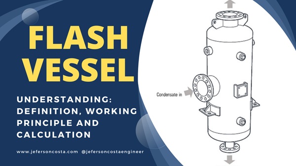
A flash vessel is a pressure container used to separate a vapor-liquid mixture into its individual vapor and liquid components. This separation occurs due to a pressure drop, causing a portion of the liquid to vaporize or “flash” into vapor. The flash vessel efficiently separates these two phases based on their density differences.
Flash Vessel Working Principle
The working principle of a flash vessel is based on the partial vaporization of a liquid stream. When a high-pressure liquid enters the vessel and experiences a pressure drop, it causes a portion of the liquid to evaporate or flash into vapor. The resulting vapor and liquid phases have different densities and can be separated gravitationally within the vessel.
Here’s a step-by-step breakdown of the process:
- Inlet Stream: A high-pressure, high-temperature liquid mixture enters the flash vessel through an inlet pipe.
- Pressure Drop: The liquid undergoes a sudden pressure drop upon entering the vessel, causing a portion of the liquid to vaporize.
- Phase Separation: The vapor rises to the top of the vessel while the remaining liquid, now at a lower temperature and pressure, settles at the bottom.
- Outlet Streams: The vapor is drawn off from the top of the vessel, and the liquid is withdrawn from the bottom.
Flash Vessel Function
The primary functions of a flash vessel include:
- Phase Separation: Separating vapor and liquid phases in a mixture.
- Pressure Reduction: Reducing the pressure of a liquid stream, causing partial vaporization.
- Temperature Control: Regulating the temperature of the liquid stream through vaporization.
Flash Vessel Design
Designing a flash vessel involves several key considerations:
- Pressure and Temperature: The vessel must withstand the operating pressures and temperatures.
- Material Selection: The construction material must be compatible with the fluid’s chemical properties.
- Volume and Residence Time: Sufficient volume to allow adequate residence time for phase separation.
- Nozzle Design: Properly sized inlet and outlet nozzles to ensure efficient flow and separation.
- Vapor-Liquid Interface: Ensuring a clear interface between the vapor and liquid phases to prevent entrainment.
Flash Vessel Sizing Calculation
Flash vessel sizing is critical to ensuring efficient phase separation and minimizing operational issues. One method to size a flash vessel involves using terminal velocity for the vapor phase. Below are the steps for sizing a flash vessel based on terminal velocity, followed by an example calculation with a ratio of diameter to liquid height (D/H) between 2 and 4.
- Determine the Terminal Velocity:
- Calculate the terminal velocity (Vt) of the vapor phase using the Stokes’ law or empirical correlations based on the properties of the vapor and liquid phases.
- Calculate Volumetric Flow Rates:
- Determine the volumetric flow rates of the vapor (Qv) and liquid (Ql) phases.
- Determine Cross-Sectional Area:
- Calculate the required cross-sectional area () of the vessel to ensure that the vapor velocity is below the terminal velocity.
- Determine Vessel Diameter:
- Using the cross-sectional area, calculate the vessel diameter ().
- Determine Vessel Height:
- Use the liquid holdup volume and the diameter to calculate the vessel height (), ensuring the D/H ratio is between 2 and 4.
- Verify the Design:
- Ensure that the calculated dimensions meet the design and operational requirements.
VESSEL SEPARATOR/FLASH VESSEL SIZING ON ASPEN HYSYS
Flash Vessel Calculation Example
Given Data:
- Inlet mass flow rate (m˙in): 1000 kg/h
- Vapor mass flow rate (m˙v): 200 kg/h
- Liquid mass flow rate (m˙l): 800 kg/h
- Vapor density (rho_v): 2 kg/m³
- Liquid density (rho_l): 800 kg/m³
- Desired residence time: 5 minutes = 300 seconds
- Terminal velocity (Vt): 0.15 m/s
- Calculate Volumetric Flow Rates:
- Vapor volumetric flow rate:
Qv = m˙v/rho_v = (200 kg/h)/(2 kg/m3) = 100 m3/hConvert to seconds:
Qv = (100 m3/h)/(3600 s/h) ≈ 0.0278 m3/s
- Liquid volumetric flow rate:
Ql = m˙l/rho_l = (800 kg/h)/(800 kg/m3) = 1 m3/hConvert to seconds:
Ql = (1 m3/h)/)(3600 s/h) ≈ 0.000278 m3/s
- Vapor volumetric flow rate:
- Calculate Required Cross-Sectional Area:
- Using the terminal velocity: A = Qv/Vt = (0.0278 m3/s)/(0.15 m/s) ≈ 0.1853 m2
- Determine Vessel Diameter:
- From the cross-sectional area: A=π(D^2)/4 ; D=(4Aπ)^(1/2) = (4×0.1853 m2/π)^(1/2) ≈ 0.486 m
- Calculate Liquid Volume for Desired Residence Time:
- Liquid volume: Vl = Ql×t = 0.000278 m3/s × 300 s = 0.0834 m3
- Determine Vessel Height:
- For a D/H ratio of 2:
H = Vl/A = (0.0834 m3)/(0.1853 m2) ≈ 0.45 m; H/D=0.45 m/0.486 m ≈ 0.926 (which is not between 2 and 4)
- For a D/H ratio of 4 (calculate diameter again):
H = 4×D = 4×0.486 ≈ 1.944 mVerify the volume with the new height:
V = A×H = 0.1853 m2×1.944 ≈ 0.360 m3; New Diameter: [4×0.0834 m3/(π×4)]^(1/3) ≈ 0.299 m; New Height: 4×0.299 ≈ 1.196 m
- For a D/H ratio of 2:
By following the above steps, we can size a flash vessel to ensure proper phase separation.
In this example, the flash vessel diameter ranges from approximately 0.299 meters to 0.486 meters, and the corresponding heights are 1.196 meters for a D/H ratio of 4 and 0.45 meters for a D/H ratio of 2.
These dimensions are based on maintaining the vapor velocity below the terminal velocity and ensuring sufficient liquid residence time. Adjustments may be necessary based on specific operational requirements and constraints.
VESSEL SEPARATOR/FLASH VESSEL SIZING ON ASPEN PLUS
Useful links and Materials:
HYSYS Tutorial for Beginners | Aspen Hysys training
DWSIM process simulator tutorial | DWSIM Pump and Pump Curve simulation