Pressure monitoring and control is very important in plant design and operation. This variable influences reactions, fluid flow, separation process, fluid properties and so on. Based on that, let’s see some issues that chemical process engineers must be aware of during the piping and instrumentation diagram (P&ID) development.
PS. If you have any issue about P&ID see What is P&ID: PIPING and Instrumentation Diagram or PROCESS and Instrumentation Diagram?
In general, operation pressure will be defined according to customer requirement at battery limits and process efficiency defined by the supplier´s technology. For instance:
Pressure at battery limit
Air separation unit (ASU) can produce high purity nitrogen gas at very low pressure at the column outlet (below <1 barg), however, a customer requires nitrogen supply at 17 barg +/- 5% at the battery limit. To increase product pressure a compressor needs to be added downstream air separation column to build up nitrogen pressure. The compressor discharge setting depends on the pressure drop between the equipment and battery limits.
Process efficiency
Very low biogas pressure from landfill (less than 0.5 barg) is fed to a biomethane plant for processing. Although customer requires 14 barg +/- 5% at battery limit, the best efficiency for removing CO2 from CH4 (methane) using a physical solvent is around 30 barg. In order to reach the best separation efficiency, a compressor is added upstream purification unit to built gas pressure. The gas pressure is reduced at the battery limit pressure to comply with customer requirements.
Pressure in the P&ID
To start with, the chemical process engineer must be alert to the thermodynamic properties of the fluid according to operating pressure. For instance, a pressure decrease may lead to the vaporization of a liquid or liquefaction of gas. This kind of information is shown in the heat and material balance of the process flow diagram (PFD).
In the P&ID development, care must be taken to the design pressure because material thickness and piping pressure ratings are based on this. One way to identify design pressure is to look for pressure relief device (PRD) setpoint and pipe name. Pipe name code usually has info about pressure rating. PRD setpoint is based on equipment/system MAWP at a defined temperature.
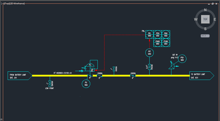
To monitor, control and for safety reasons you need to represent in the P&ID the pressure indicator, pressure transmitters, high-pressure alarm, low-pressure switch and so on, only to name a few. Now, let’s see some drawings shown in a P&ID and a short description of them.
Pressure Symbols in a P&ID
Indication
Pressure indication can be only local (PI) or local with a transmitter (PIT) to a supervisory or HMI, or virtual (PI) according to a signal from a pressure transmitter. In any case, operation needs to be able to read pressure measurement.
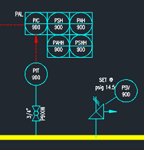
Alarms and Shutdown
Alarm and Shutdown representation may differ depending on Company and industry code and standards. In general, PAH refers to alarm action (H = high, L=low) while PAHH refers to Shutdown action. It means that if the PAH setpoint is reached the plant will keep running although a process disturbance beyond operation range was identified. If PAHH set point is reached process is shutdown to prevent an unsafe condition that can lead to an accident. For instance, flange rupture. You may find also PSH and PSHH associated with PAH and PAHH, respectively. These switches can be physical and virtual.
PAH = high pressure alarm
PAHH = very high pressure alarm
PAL = Low pressure alarm
PALL = very low pressure alarm
Control
For remote control of pressure, most often a PIC is added to the P&ID. In this case, it means that there is a pressure measurement (PT or PIT) whose signal is sent to the controller. The controller will send a signal for a valve or equipment in order that pressure increases or decreases to reach the setpoint. PIC means that you can see pressure indication during control.
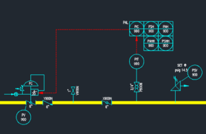
Signal to a Pressure Control Valve


1 Comment