Imagine you have a condenser at barometric or vacuum conditions and your boss asks you to design a drain system. How would you proceed with?
Barometric condensers are equipment used to desuperheat and condense incoming vapors by cooling. 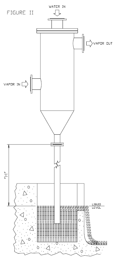 This kind of equipment can be part of ejector system used to improve yield performance of crude vacuum unit heavy vacuum gas-oil (HVGO).
While the ejectors and condensers are designed by vacuum-jet system vendor, the process engineer is responsible for designing the seal legs, the seal drum, and determining the condenser elevations. The condensing fluid and condensed vapors from this process are removed by either the use of a tailpipe/barometric leg or a pump.
In this post, I will share with you consideration about barometric leg calculations and design.
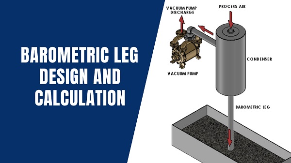
The seal leg, tailpipe or barometric leg is basically a condensate drain that consists of a leg pipe between the condenser and the receiver. The condensate drains by gravity and drops down through the leg into the receiver, also known as hotwell, where the condensate is collected.
The decrease of volume by cooling or intentionally operated by vacuum creates a situation where the condensate is under vacuum in the condenser and is trying to move toward a receiver tank that is under atmospheric or positive pressure. As the receiver operates above vacuum conditions, the process engineer must define the pipe leg (static head pressure) to overcome the differential pressure and prevent backflow of condensate. The condenser must be located higher than the hotwell to allow enough static head pressure of the condensate to overcome the pressure differential.
Rule of thumb
In the “understand vacuum-system fundamentals” paper, the authors share rules of thumb for barometric leg height. According to the authors, improper barometric leg (condensate drain) layout has a negative effect on condenser performance. Condensate drains by gravity, so the barometric leg must be high enough to ensure that condensate does not enter and flood the condenser. Flooding lower tubes makes them ineffective for heat transfer. The barometric legs should be at least 34 ft above the condensate receiver for 100% water condensate. With mixed water and hydrocarbon condensates, a barometric leg of at least 42 ft is required. If condenser flooding occurs, check the drain legs for blockage. Also, horizontal drain leg runs are not recommended because they are susceptible to gas pockets. If a condensate receiver operates above atmospheric pressure then the barometric leg height must be increased.
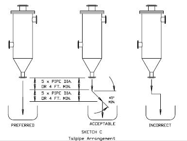
The tailpipe arrangement is very crucial and should not contain any horizontal runs. The ideal is straight down and the acceptable is 45-degree minimum off the horizontal, and the change in direction must be 5 pipe diameters or 4 feet minimum away from the water outlet flange and between all changes in direction.
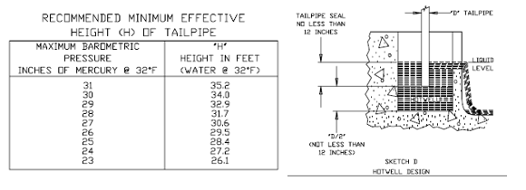
Graham vacuum and heat transfer, in its barometric condenser operation, maintenance and installation manual recommends that the size of the hotwell shall be such that the volume of the water measured from the bottom of the tailpipe to the point of overflow is at least equal to 1.5 times the volume of the minimum recommended height of the tailpipe; in no case should the seal height be less than 12”. The system is effectively sealed by submerging the leg pipe below the hotwell liquid level, so atmospheric air/vent gases can’t be “pulled” back into the piping. Other references recommend barometric pipe seal height should be no less than 6”.
Although some rules of thumbs are available, as a chemical process engineer, you must understand that the calculation of barometric leg height depends on local pressure conditions (barometric), operating conditions, and fluid properties.
Engineering calculations
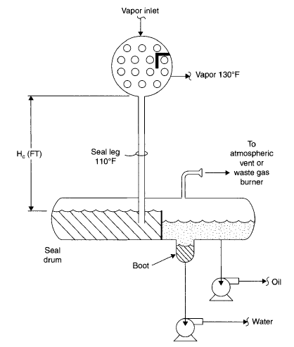
In the book “Troubleshooting Vacuum Systems: Steam Turbine Surface Condensers and Refinery Vacuum Towers”, Norman P. Lieberman gives guidance to seal leg design. According to the author, to locate the condensers high enough so that condensate drains by gravity into the seal drum, in a system venting to the atmosphere, the minimum height of the condenser bottom above the maximum liquid level in the seal pot, feet. (Hc) should follow the following relationship with pressure in the condenser, inches of Hg (Pc).
Hc =1.1(Pc).
Note that Hc is defined based on condenser bottom and seal drum level. Total barometric leg length must consider pipe seal length under seal drum as shown in the picture below.
Another equation to barometric leg height calculation is Hc = [(Pman + Pbarometric – Pcondenser)/SGt] x WC.
Hc = barometric leg heigh above seal drum level (ft)
Pman = seal drum manometric pressure (psig)
Pbarometric = atmospheric pressure in the location (psia)
Pcondenser = condenser absolute pressure (psia)
SGt = specific gravity of water in the Condenser
WC = feet of cold water, (2.31 ft/psi @60F)
For condensing fluids different than water, barometric leg correction can be done using Hf = Hc x (SGt/SGf), where SGf is the specific gravity of the fluid at the operating temperature in the Condenser.
As you can see, for fluids lighter than water, Hf > Hc.
Just a reminder, to transform pressure to column of liquid, use P = SG.g.H. where g is the acceleration of gravity, P is absolute pressure and H is the height of liquid.
Last consideration and references
Barometric leg height definition is very important to condenser performance under vacuum conditions because the wrong assumption can lead to condenser flood and poor plant performance. The chemical process engineer must be familiar with this kind of calculation not only to do the design but also, in the case of the third part project review and evaluation of operations performance.
Below are the references used for this post and affiliate links to have access to the files.
- Troubleshooting Vacuum Systems: Steam Turbine Surface Condensers and Refinery Vacuum Towers. Norman P. Lieberman
- Understand vacuum-system fundamentals. Hydrocarbon Processing, October 1994.
- BAROMETRIC CONDENSER OPERATION, MAINTENANCE AND INSTALLATION MANUAL. Graham Vacuum and Heat Transfer.
- BAROMETRIC LEG. Dekker Vacuum Technologies.