HOW TO DO NPSH AVAILABLE CALCULATION FAST AND EASILY
Net Positive Suction Head Available or just NPSH available is very important information to any chemical process engineer. This information is used by operation personnel to evaluate if a pump is cavitating, and in plant design, it is used by chemical process engineers to select the correct pump and avoid cavitation. NPSH is a term describing conditions related to cavitation, which is undesired and harmful.
In the following lines, I will teach you step by step how to perform NPSH available calculation as a chemical process engineer in plant design.
WHAT IS PUMP CAVITATION
To start with, it is important you understand what is cavitation. In a few words, cavitation is the creation of vapour bubbles in areas where the pressure locally drops to the fluid vapour pressure. The extent of cavitation depends on how low the pressure is in the pump. Cavitation generally lowers the head and causes noise and vibration.
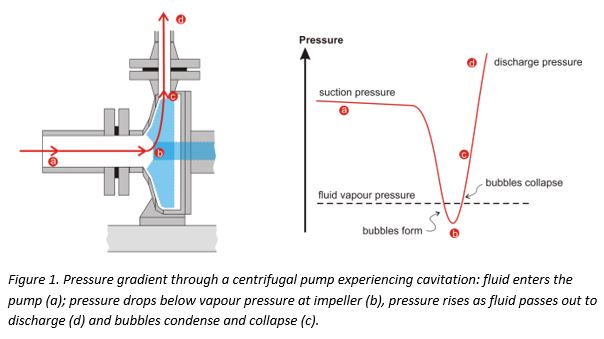
If the pressure of the fluid at any point in a pump is lower than its vapour pressure, it will literally boil, forming vapour bubbles within the pump. The formation of bubbles leads to a loss in throughput and increased vibration and noise. However, when the bubbles pass on into a section of the pump at higher pressure, the vapour condenses and the bubbles implode, releasing, locally, damaging amounts of energy. This can cause severe erosion of pump components.
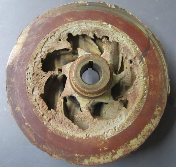
Pump Cavitation Damaged
As chemical process engineers in plant design or operations, we must guarantee that liquid operating pressure at pump suction does not fall below its bubble point. That is where NPSH available works.
NET HEAD SUCTION HEAD (NPSH) DEFINITION
There are two expressions related to NPSH: NPSH required and NPSH available.
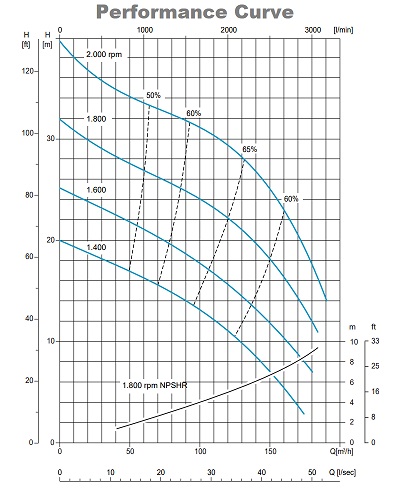
The NPSHr (required) is the head value at the suction side of a pump) required to keep the fluid away from cavitating. This information is always provided by the pump manufacturer, although there is some correlation developed by researchers, and can be found in the pump performance curve. NPSHr increases with pump flow.
The NPSHa (available) is a measure of how close the fluid at a given point is to flashing, and so to cavitation. This value is defined based on process information according to fluid pressure and temperature.
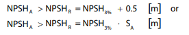
Important to mention that both values are defined at the pump suction nozzle. To prevent damage, NPSHa shall be higher than NPSHr. To guarantee that, the chemical process engineer performs the NPSH calculation, reduces the safety margin from the NPSHa value, and selects the pump that has an NPSHr lower than the NPSHa – safety margin.
A minimum safety margin of 0.5 m is recommended. Depending on the application, a higher safety level may be required. For example, noise sensitive applications or in high energy pumps like boiler feed pumps, European Association of Pump Manufacturers indicate a safety factor SA of 1.2-2.0 times the NPSHr.
NPSH AVAILABLE FORMULA / EQUATION CALCULATION
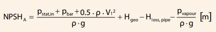
To perform NPSHa calculation I recommend you to use the equation below that takes into account only the vapor pressure of the fluid at the present temperature, the absolute pressure at the inlet flange, the mass density of the fluid, and the acceleration of gravity.
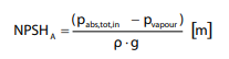
The absolute pressure at the pump inlet will depend on the process arrangement.
NPSHa CALCULATION EXAMPLES
Let’s take a look at two examples extracted from Grundfos Centrifugal Pump ebook:
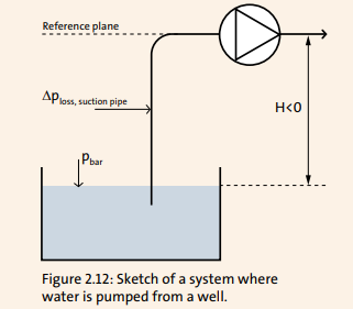
Example 2.1 Pump drawing from a well
A pump must draw water from a reservoir where the water level is 3 meters below the pump. To calculate the NPSHA value, it is necessary to know the friction loss in the inlet pipe, the water temperature and the barometric pressure, see figure 2.12
Water temperature = 40°C
Barometric pressure = 101.3 kPa
Pressure loss in the suction line at the present flow = 3.5 kPa.
At a water temperature of 40°C, the vapour pressure is 7.37 kPa and ρ is 992.2kg/m3.
For this system, the NPSHA expression in formula (2.16) can be written as:
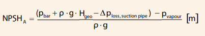
Hgeo is the water level’s vertical position in relation to the pump. Hgeo can either be above or below the pump and is stated in meter [m]. The water level in this system is placed below the pump. Thus, Hgeo is negative, Hgeo = -3m.
The system NPSHA value is:

NPSHa = 6.3m
The pump chosen for the system in question must have a NPSHR value lower than 6.3 m minus the safety margin of 0.5 m. Hence, the pump must have a
NPSHR value lower than 6.3-0.5 = 5.8 m at the present flow.
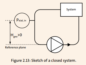
Example 2.2 Pump in a closed system
In a closed system, there is no free water surface to refer to. This example shows how the pressure sensor’s placement above the reference plane can be used to find the absolute pressure in the suction line, see figure 2.13.
The relative static pressure on the suction side is measured to be pstat, in = -27.9 kPa2. Hence, there is negative pressure in the system at the pressure gauge. The pressure gauge is placed above the pump. The difference in height between the pressure gauge and the impeller eye Hgeo is therefore a positive value of +3m. The velocity in the tube where the measurement of pressure is made results in a dynamic pressure contribution of 500 Pa.
Barometric pressure = 101 kPa
Pipe loss between measurement point (pstat,in) and pump is calculated to Hloss,pipe = 1m.
System temperature = 80°C
Vapour pressure pvapour = 47.4 kPa and density is ρ = 973 kg/m3.
For this system, formula 2.16 expresses the NPSHA as follows:
Inserting the values gives:
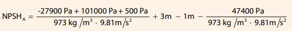
NPSHA = 4.7m
Despite the negative system pressure, a NPSHA value of more than 4m is available at the present flow
WAYS TO INCREASE NPSH (REQUIRED/AVAILABLE)
Frequently during the early design stage of a project, the NPSH calculations are based on a preliminary piping layout. This is when engineers may find that they are dealing with low NPSH. Steps that can be taken to increase NPSH are as follows:
- Contact the piping-layout designer to see whether they can increase the elevation of the suction vessel;
- Check whether increasing the size of the suction piping reduces the pressure drop and increases the NPSH available;
- Consult with the vendor to see if a bigger impeller is available. Pumps with larger impellers have better NPSH values. However, the penalty for bigger impellers is a higher power consumption;
- Check with the vendor for a slower-speed motor. Pump manufacturers may suggest a slow-speed motor to reduce NPSH-related problems. With a slower motor, high static head is available at the suction and improves NPSH;
- Determine whether the pump can be physically lowered inside a pit or sump to increase the static head;
- If the process allows, lower the temperature of the pumping process to decrease vapor pressure. A practical example is a molten-sulfur pump in a batch process that cavitated when the temperature of the reactor was high; the high temperature led to high vapor pressure and decreased NPSH availability. The plant personnel analyzed the problem, and instead of changing the pump, they decided to install a cooling-water jacket on the suction piping. The slight cooling of the fluid was enough to adequately run the pump;
- Check with the pump vendor to determine whether a flow inducer is available for your pump. If available, ask for a NPSH curve that also shows the NPSH with a flow inducer installed and check the NPSH requirement. A flow inducer is a small impeller that is installed inside the pump casing just before the pump’s main impeller. Simply, it can be defined as a small booster pump ahead of the main pump that increases the static pressure of the pumping fluid at the pump suction, reducing the NPSHr. The NPSH requirement of the flow inducer is very low.
ENGINEERING BEST PRACTICES
While calculating NPSH, follow these guidelines to ensure a quality system design:
Calculate NPSH using the low liquid level in the suction tank. This is a conservative approach, and ensures that a pump will work, even at low liquid levels. This also ensures that the liquid inventory in the storage tank is utilized to the fullest.
To avoid excessive pressure drop, design the suction piping with the minimum number of elbows and fittings. Also, suction piping should be short as possible. Target a maximum pressure drop of 0.03 bar (0.5 psi).
If the pump is connected with a reducer, use an eccentric reducer with the flat side up. This arrangement ensures that the entrained vapor bubbles will migrate back to the source instead of remaining near the pump suction. Be sure to follow any specific installation procedure that is recommended by the pump vendor.
If the line is insulated for personnel protection, consider removing the insulation and installing a metal barrier for personnel protection. Removing the insulation will help the fluid to cool down, lower the vapor pressure and achieve a higher value for NPSH available.
A design margin of at least 0.6 – 0.9 m (2–3 ft) should be allowed between the NPSH required and the NPSH available. The NPSH available should always be greater than the NPSH required.
ASPEN HYSYS NPSHa CALCULATION ADVICE
Care must be taken when using Aspen Hysys process simulation software to perform NPHSa calculation. First, because on NPSHa equation used by Aspen Hysys takes into account the velocity head at pump suction. as shown in the equation below.
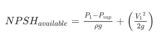
When performing the heat and material balance (HMB) of a process, at the initial stages of plant design, information regarding pump nozzles is not available. However, Aspen Hysys uses a standard value to pump nozzle of 0,5 m. As velocity increases NPSHa, the wrong assumption in fluid velocity can lead to false results.
Another point of attention is that Aspen Hysys does not take into account the height of liquid in any vessel. Because of that, NPSHa for liquids at boiling point is not easily taken from standard Aspen Hysys inputs/outputs.
NPSHA CALCULATION WITH EXCEL SPREADSHEET AND ASPEN HYSYS
OTHERS POST RELATED TO PUMPS:
3x FREE PUMP SELECTION SOFTWARES FOR CHEMICAL PROCESS ENGINEERS
Pump Discharge Always Need a PSV?
REFERENCES
Grundfos Pump Handbook
GPSA Electronic Databook
Calculate NPSH with Confidence by Asif Raza.