HOW TO START NATURAL GAS DEHYDRATION DESIGN AS A CHEMICAL PROCESS ENGINEER, EVEN IF YOU ARE A FRESH ENGINEER
Do you not know how to start to design a natural gas dehydration unit?
This can be a big problem, especially if you are looking for a job in the oil and gas industry. Not being familiar with natural gas dehydration unit can kill your chances of getting a job, or shifting to chemical process engineering position, in big companies like Exterran, Schlumberger, Enerflex, Pietro Fiorentinnin, QB Johnson Manufacturing, Frames Group, Axens, KW International, Propak Systems, Alco Group, Croft Production Systems, Nihon Seiki, ALLIA France.
But do not be desperate, you are very lucky for accessing my blog (www.jefersoncosta.com/blog)! Today, I will share with you the technical aspects for designing of natural gas dehydration units. Keep reading and I will teach you how chemical process engineers start a natural gas dehydration unit design. I will cover the following topics with you:
- Dehydration technique selection
- Glycol Dehydration Systems
- Setting TEG concentration
- TEG circulation definition
- Absorber diameter calculation
- Absorber height calculation
- Flash vessel sizing conditions
- TEG regeneration design
- TEG Dehydration process with Aspen HYSYS
- TEG Dehydration design framework
- Case Study Homework
- References
NATURAL GAS DEHYDRATION UNITS
Dehydration technique selection
Gas dehydration is used to remove water vapour from gas streams for applications such as pipeline transportation and cryogenic processing. Absorption into glycols is the favoured dehydration method for pipeline transportation, where typically the allowable moisture content of transmission natural gas ranges from 4 to 7 pounds per MMSCF (64–112 mg/m3). Water content may leads to solid hydrate formation, corrosion of pipelines & process plants particularly in the presence of CO2 or H2S, slugging and erosion problems in the flow lines. However, for deep dehydration applications such as LNG processing, a moisture content of usually less than 0.1 ppmv is required.
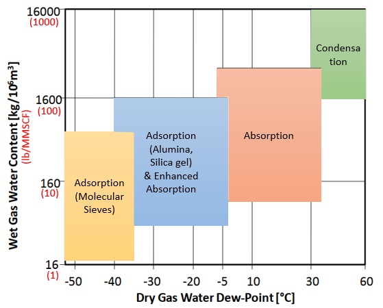
The first thing you must deal with as chemical process engineer is the selection of the technology or technique to be used in the natural gas dehydration unit. Techniques for dehydrating natural gas include: Absorption using liquid desiccants, Adsorption using solid desiccants, Dehydration with CaCl2, Dehydration by refrigeration, Dehydration by membrane permeation, Dehydration by gas stripping, and Dehydration by distillation. Each one of these techniques has their pros and cons.
To select the one or combination of techniques that fit your process you must have raw natural gas characterization (feed) and also natural gas requirements (product). Basic information for feed and product are: flow, pressure, temperature and composition. These information will allow you to calculate the amount of water present in the natural gas and also identify the contaminants and their amount. Moreover, based on them, you will define the techniques to be applied to the dehydration and need for pre-treatment. The following chart will help you on this selection.
Glycol Dehydration Systems
The most common method for dehydration in the natural gas industry is the use of a liquid desiccant contactor–regeneration process. In this process, the wet gas is contacted with a lean solvent (containing only a small amount of water). The water in the gas is absorbed by the lean solvent, producing a rich solvent stream (one containing more water) and a dry gas.
Glycols are typically used for applications where dew point depressions of the order of 60° to 120°F are required. Diethylene glycol (DEG), triethylene glycol (TEG), and tetraethylene glycol (TREG) are used as liquid desiccants, but TEG is the most common for natural gas dehydration. With a conventional TEG unit dry gas water contents down to 150 ppm can be achieved, although often limited by a dewpoint depression of roughly 90 oF. The latter is due to the fact that the absorption efficiency of TEG depends on the temperature and pressure.
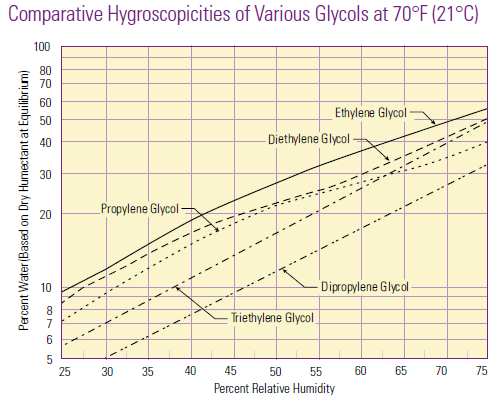
Hygroscopicity is a general term used to describe a material’s ability to absorb moisture from the environment. There is no standard quantitative definition of hygroscopicity, so generally the qualification of hygroscopic and non-hygroscopic is determined on a case-by-case basis.

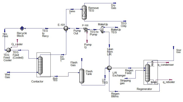
In the above process flow diagram, the regenerated glycol is pumped to the top tray of the contactor (absorber). The glycol absorbs water as it flows down through the contactor countercurrent to the gas flow. Water-rich glycol is removed from the bottom of the contactor, passes through the reflux condenser coil, flashes off most of the soluble gas in the flash tank, and flows through the rich-lean heat exchanger to the regenerator. In the regenerator, absorbed water is distilled from the glycol at near atmospheric pressure by application of heat. The regenerated lean glycol flows through the rich-lean and glycol cooler exchanger for cooling before being recirculated to the contactor by the glycol pump.
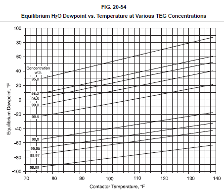
2.1 Setting TEG concentration
Evaluation of a TEG system involves first establishing the minimum TEG concentration required to meet the outlet gas water dewpoint specification. Fig. 20-54 shows the water dewpoint of a natural gas stream in equilibrium with a TEG solution at various temperatures and TEG concentrations. Fig. 20-54 can be used to estimate the required TEG concentration for a particular application or the theoretical dewpoint depression for a given TEG concentration and contactor temperature. Actual outlet dewpoints depend on the TEG circulation rate and number of equilibrium stages, but typical approaches to equilibrium are 10-20°F.
2.2 TEG circulation definition
Once the lean TEG concentration has been established, the TEG circulation must be determined. In general, the lower the circulation rate the lower the operating cost for the glycol dehydration unit. The circulation rate for the rich glycol is typically between 17 and 33 L of glycol per kilogram of water in the inlet gas (2–4 gal/lb of water). Circulation rates less than 17 L/kg (2 gal/lb) are not recommended.
In addition to absorbing water vapor, some hydrocarbons are also absorbed. As an approximate rule of thumb, TEG typically absorbs about 0.007 m3/L (1 SCF of sweet gas per gallon of glycol) at 7 MPa (1000 psia) and 38 °C (100 °F). The solubility will be significantly higher if the gas contains H2S and CO2.
2.3 Absorber diameter calculation
The contactor is a typical absorber tower properly sized with the process objective in mind. The feed gas flow rate is the most significant factor in determining the diameter of the contactor.
Absorber diameter is set by the gas velocity. Sizing is identical to that outlined for separators. The diameter of the contactor can be approximated using Fig. 6.2.

2.4 Absorber height calculation
The outlet gas water content specification is the key to determine the contactor height, although other factors contribute as well. The contactor is made up of a number of equilibrium stages, enough to ensure mass transfer from the gas phase to the liquid is such that the outlet gas is at the desired water specification.
Conversion from equilibrium stages to actual trays can be made assuming an overall tray efficiency of 25-30%. For packing, Height of Packing Equivalent to a Theoretical Plate (HETP) varies with TEG circulation rate, gas rate, and gas density but a value of about 60 inches is usually adequate for planning purposes. When the gas density exceeds about 6 lb/ft3 (generally at very high pressures), the above conversions may not provide sufficient packing height and number of trays.
Typical tray spacing in TEG contactors is 24 inches. Therefore, the total height of the contactor column will be based on the number of trays or packing required plus an additional 6-10 ft to allow space for vapor disengagement above the top tray, inlet gas distribution below the bottom tray, and rich glycol urge volume at the bottom of the column.
2.5 Flash vessel sizing conditions
The rich glycol is withdrawn from the bottom of the contactor, usually on level control. Typically the lean glycol is preheated, often by passing it through tubes in the overhead condenser at the top of the still column. Then it is flashed at low pressure in a flash tank where most of the volatile components (entrained and soluble) are vaporized. Flash tank pressures are typically in the range of 300–700 kPa (50–100 psia).
Flash tank sizing should be sufficient to degas the glycol solution and skim entrained liquid hydrocarbons, if necessary. A minimum retention time of 3-5 minutes is required for degassing. If liquid hydrocarbons are to be removed as well, retention times of 20-30 minutes may be required for adequate separation. Flash tank pressures are typically less than 75 psia.
2.6 TEG regeneration design
A basic regeneration unit is made up of a combination of a fired reboiler, located at the lower section of a horizontal vessel with a vapor space above the tube bundle, a distillation column (still column) connected vertically to the vapor space of the reboiler vessel, and a surge tank located below the reboiler.
The size of the regenerator is determined by a balance between the solvent circulation rate, the amount of water vapor in the gas stream, and the reboiler temperature. The standard TEG dehydration unit operates effectively at a reboiler temperature around 175 °C (350 °F), or about 20 °C (30 °F) below the decomposition temperature of TEG. Boiling of TEG at 400°F and 1 atmosphere will provide about 98.6 wt% glycol. Regeneration at higher altitude will result in higher concentrations at 400°F or a reduced regeneration temperature at the same concentration.
Regenerator sizing requires establishing the reboiler duty and, when high TEG concentrations are required, providing sufficient stripping gas.
The duty for the regenerator reboiler can be estimated using the following equations: Q = 560L; where Q is the duty in kJ/h and L is the circulation rate, in L/min, calculated as specified previously. Or in American Engineering units: Q = 2000L where Q is the duty in Btu/h and L is the circulation rate, gpm.
Dehydration with Aspen HYSYS
Aspen HYSYS has historically employed the glycol property package for TEG. With the addition of the Cubic-Plus-Association (CPA) package in V10 and above, Aspen HYSYS can be used to model dehydration with TEG, MEG and DEG.
In earlier versions of Aspen HYSYS, the Glycol property package is the recommended thermodynamic model for simulation of TEG dehydration process. Good results have been reported in prediction of BTEX emission and water content in TEG dehydration units. However, some deficiencies have been reported, such as when methanol is present. The Glycol property package is also limited to TEG only; EG and DEG are not supported.
In Aspen HYSYS V10, it was decided to build on earlier work using the CPA property package to model methanol-related systems and extend it to fully support EG, DEG and TEG. The CPA equation of state is widely used in the industry and has been widely studied with many published parameters. Therefore, it is a good model to adopt for modeling glycol dehydration processes. It can also be readily extended to model additional components and processes in the future.
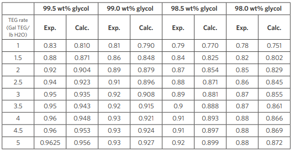
Results using CPA property package are compared with plant data in Table 5. For clarity, the results in Table 5 shows comparison between data and CPA at four TEG concentrations of 98.0, 98.5, 99.0 and 99.5 percent by weight at a TEG rate that varies from 0 to 6 (gal/lb water).
Table 5: Comparison of CPA-predicted water removal fraction from contactor against data with different lean glycol concentration and TEG circulation rate (100°F, 1000 psia). Contactor used has two equilibrium stages.
TEG Dehydration design framework
Design companies use process simulation software to improve process engineering productivity. As a chemical process engineer you need to develop heat and material balance, engineering drawing and specification datasheets.
To finish this post, let me summary the framework for natural gas dehydration unit design, considering the application of TEG absorption using Aspen Hysys:
Verify natural gas feed characteristics;
Calculate amount of water in the feed stream;
Confirm natural gas product specification;
Use the chart to pre-select available technique for dehydration;
Select TEG concentration to achieve desired dewpoint;
Use Aspen Hysys to perform process simulation (heat and material balance);
Case Study Homework
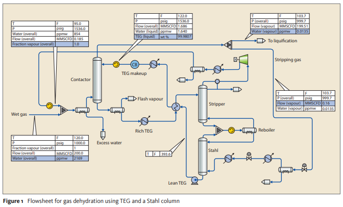
Perform a process simulation to a TEG Dehydration Unit based on the below process flow diagram and the following feed gas composition (mol%): Water 0.217 (2169 ppmv), CO₂ 4.989E-3 (50 ppmv), Methane 89.299, Ethane 5.684, Propane 2.108, N-Butane 0.589, Isobutane 0.340, N-Pentane 0.200, Isopentane 0.200, N-Hexane 0.549, Nitrogen 0.809.
FREE ONLINE TRAINING: PLANT DESIGN FOR CHEMICAL PROCESS ENGINEERS
Get instant access to the free training PLANT DESIGN FOR CHEMICAL PROCESS ENGINEERS and leverage your chemical process engineering and plant design skills at https://jefersoncosta.com/plant-design-free-training-for-chemical-process-engineer/
Help me to reach more chemical process engineers around the world by sharing this post with other students, graduates and engineers interested in chemical process engineering and plant design. 🙂
References
GPSA Electronic Data Book
CAPEX and OPEX Considerations for Gas Dehydration Technologies. Joeri Olijhoek at all. Gas Mexico Congress
A Comparison of Natural Gas Dehydration Methods. Ebrahiem E. Ebrahiem. MJET.
NATURAL GAS HYDRATES A Guide for Engineers. JOHN CARROL. Elsevier.
Stahl columns – an alternative to molecular sieves? JEFFREY A WEINFELD at all. Digital Refining.
Triethylene Glycol. A complete manual. Dow.
Dehydration with Aspen HYSYS®: Validation of the CPA Property Package. ASPENTECH.