5 HEAT EXCHANGERS´ RULE OF THUMB DESIGN FOR CHEMICAL PROCESS ENGINEERS
Working as a chemical process engineer in plant design since 2007, I have been dealing with heat exchangers for steam methane reforming hydrogen production, air separation units (oxygen, nitrogen and argon production), CO2 liquefaction plants, renewable natural gas (biomethane) production and so on. Based on my design, commissioning, startup, and plant troubleshooting experience, I can guarantee that Heat Exchanging is a very important subject for students, graduates and engineers really interested in working with chemical process engineering and plant design.
Today, I will share with you 5 rules of thumb for heat exchanger design.
WHAT IS A HEAT EXCHANGER
Starting from the beginning, a heat exchanger is equipment used to transfer heat between a source and a working fluid. Typical applications involve heating or cooling of a fluid stream of concern and evaporation or condensation of single or multicomponent fluid streams. The fluids may be separated by a solid wall to prevent mixing or they may be in direct contact. Heat exchangers are one of the basic equipment in chemical, petrochemical, oil & gas, air separation, and many other industries. Their design start with the chemical process engineer performing the plant heat and material balance, most often, using process simulation software (Aspen Hysys, Unisim Design, DWSim, Aspen Plus, etc). Mechanical design can be performed using EDR and HTRI software, and usually, it is not the chemical process engineer’s responsibility.
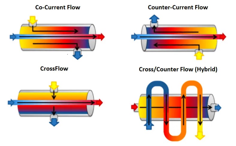
RULE #1: Take true countercurrent flow in a shell-and-tube exchanger as a basis.
There are three primary classifications of heat exchangers according to their flow arrangement: parallel-flow, counter-flow, and cross-flow arrangement. In parallel-flow heat exchangers, the two fluids enter the exchanger at the same end, and travel in parallel to one another to the other side. In counter-flow heat exchangers the fluids enter the exchanger from opposite ends. In a cross-flow heat exchanger, the fluids travel roughly perpendicular to one another through the exchanger.
The counter current design is the most efficient, in that it can transfer the most heat from the heat (transfer) medium per unit mass due to the fact that the average temperature difference along any unit length is higher.
RULE #2: The tube side is for corrosive, fouling, scaling, and high pressure fluids.
To minimize costs, if a fluid is highly corrosive, it can be confined within the tubes of the heat exchanger, requiring only the tubes, tubesheets (possibly only facing the corrosive side), tube channels, and piping to be constructed with a corrosion-resistant alloy. Similarly, if one fluid operates at significantly higher pressure than the other, it should be directed into the tubes to avoid thicker material (more expensive) to the shell. Additionally, if one fluid is prone to severe fouling compared to the other, it is beneficial to position it in the tubes. Tubes are easier to clean, particularly when mechanical methods like brushes are employed.

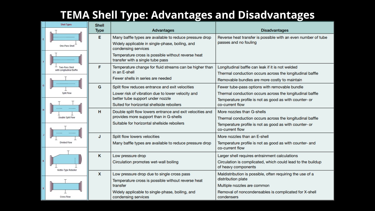
RULE #3: Shell side is for viscous and condensing fluids, and for fluid with very limited allowable pressure drop.
The shell type has a significant effect on the flow configuration and thermal performance of the heat exchanger. The Tubular Exchanger Manufacturers Association (TEMA) has developed a three-letter notation system to describe shell-and-tube heat exchangers, where the first letter designates the type of front head, the second letter the type of shell, and the third letter the type of rear head.
RULE #4: Double-pipe exchanger is competitive at duties requiring 9.3 – 18.6 m2 (100–200 sqft).
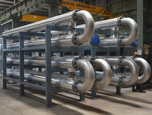
The Double Pipe type is perhaps the simplest heat exchanger and consists of a single tube or pipe, either finned or bare, inside a shell. One fluid flows in the inner pipe and the other fluid flows in the annulus between pipes in a counterflow direction for the ideal highest performance for the given surface area. However, if the application requires an almost constant wall temperature, the fluids may flow in a parallel flow direction. Flow distribution is no problem, and cleaning is done very easily by disassembly. This configuration is also suitable where one or both of the fluids is at very high pressure. Double Pipe exchanger sections are specially designed units which are normally not built to any industry standard other than ASME Code. However, TEMA tolerances are normally incorporated, wherever applicable.
Double-pipe exchangers are generally used for small-capacity applications because it is expensive on a cost per unit surface area basis.
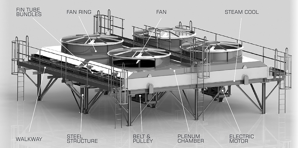
RULE #5: Air coolers: Tubes are 0.75–1.00 in. OD, total finned surface 15– 20 sqft/sqft bare surface, U = 80–100 Btu/(hr)(sqft bare surface)(°F), fan power input 2–5 HP/(MBtu/hr), approach 50°F or more.
The Air Cooler, also known as a Fin Fan Heat Exchanger, employs a set of fans to facilitate heat exchange. Its functionality revolves around circulating low-temperature atmospheric air across numerous rows of finned tubes, resulting in the cooling of internal process fluids. These coolers serve as viable alternatives to water-based cooling methods, proving especially advantageous in scenarios where a facility necessitates substantial cooling capabilities but lacks convenient access to cooling water.
RULE OF THUMB SUMMARY
Below you can see the summary for the 5 HEAT EXCHANGERS´ RULE OF THUMB DESIGN FOR CHEMICAL PROCESS ENGINEERS
RULE #1: Take true countercurrent flow in a shell-and-tube exchanger as a basis.
RULE #2: The tube side is for corrosive, fouling, scaling, and high pressure fluids.
RULE #3: Shell side is for viscous and condensing fluids, and for fluid with very limited allowable pressure drop.
RULE #4: Double-pipe exchanger is competitive at duties requiring 9.3 – 18.6 m2 (100–200 sqft).
RULE #5: Air coolers: Tubes are 0.75–1.00 in. OD, total finned surface 15– 20 sqft/sqft bare surface, U = 80–100 Btu/(hr)(sqft bare surface)(°F), fan power input 2–5 HP/(MBtu/hr), approach 50°F or more.
These are just some rules of thumb for heat exchanger design. Keep following my social media and join my online courses to learn more about chemical process engineering and plant design.
Take a look at this post: Column Reboiler and Pre-configurations on Aspen Hysys
References:
- Chemical Process Equipment Selection and Design. Stanley M. Walas
- Rules of Thumb for Chemical Engineers. Stephen M. Hall
- Chemical Process Engineering. Volume 2. A. Kayode Coker
- Selecting a Heat Exchanger Shell. Thomas G. Lestina, P.E.
- G P S A E l e c t r o n i c D a t a B o o k