
Let’s talk about process engineering drawings: Block Flow Diagram (BFD), Process Flow Diagram (PFD) and Piping/Process and Instrumentation Diagram (P&ID).
Block Flow Diagram
BFD is used in the early stage of a project. It can be drawn with boxes and there is no need for details. The main purpose of this drawing is to share the scope of design and interfaces. Keep in mind that BFD needs to have information important to management and stakeholders.
Process Flow Diagram
PDF represents heat and material balance (H&MB) and the production process also. It can be complex or not. At least 3 main info should be shown: Flow, pressure and temperatura. Basic control is added also. H&MB can be shown in the own PFD or in a different document referring PFD streams.
It is the primary document for any chemical process engineer. With a PFD we start understanding an industrial process.
The PFD is a diagram that represents the steps of a process, what kind of equipment is used, where battery limits are, show the heat and material balance stream and so on. Almost everything is a consequence of a PFD in a new project. As you may notice the PFD is one of the first documents to be developed in process design.
However, once the plant is startup some Companies do not take care of this document and as time goes by it can be lost or not represent what the plant is nowadays. Without a PFD is harder to identify where the plant bottlenecking is.
To do a “AsBuilt” of an industrial process and translate that to a PFD we need to walk through the plant, take notes, verify equipment documentation and rely on operational people. Once the draft is done it is time to identify process streams, add relevant information and notes. The PFD is done in drawing software, get a stamp with number and identification and is addressed to comments and approval.
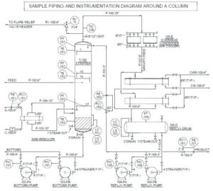
Piping and Instrumentation Diagram
P&ID is the core document for any process design. In this diagram is shown tags, manual valves, pipe and instrumentation size, control philosophy, pressure relief location and setpoint, equipment main information etc. Process engineer needs to understand and master Para&ID development.
While PFD is used to first guidance and plant performance, P&ID is the document that helps to build and operates a process plant.
As a living document, for a better understanding, P&ID can be classified in stages, for instance: Preliminary, Design, Construction and As Built.
The release of Preliminary P&ID serves as the basis for the project. Its inputs are the scope of the project, heat and material balance and contract definition. The purpose of the Preliminary P&ID is to provide information for systems, main equipment, piping, manual and automatic valves, control, safety devices and Plant interfaces without detailing them.
It is important to identify tie-in points and battery limit with Customers and Suppliers. Control valve size, PSV set point, equipment nozzle, and some packaged units info will be ON HOLD.
At this stage, the working process for developing the P&ID starts with handed marked copy, drawing templates from product line, redmarked copy from the previous project and so on.
Preliminary P&ID is the starting point for line list, instrument list and manual valve list to name just a few documents.
Classification Area Map
As a bonus for taking this far, another drawing that can be addressed to process engineer is the Classification Area Map. This document is used to guide the Electrical team and is related to flammable sources.